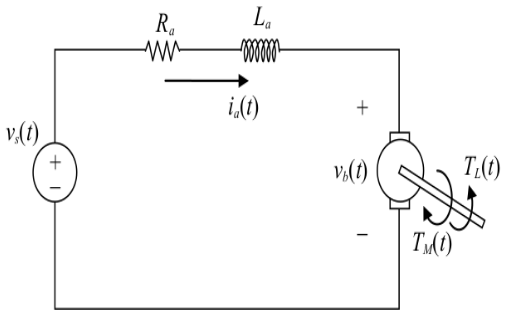
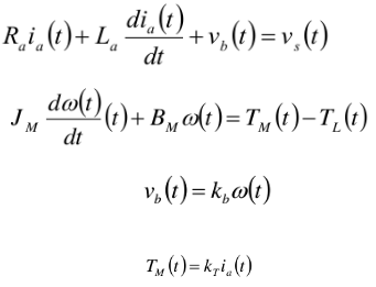
Let’s simulate the motor control system with following dynamics
First order transfer function
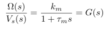
Speed , in the Laplace domain , after neglecting the armature inductance

Transfer function from volt to speed

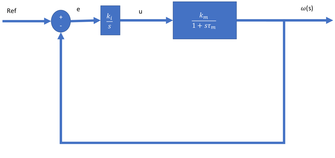
Feedback control of motor (modelled as a first order transfer system)
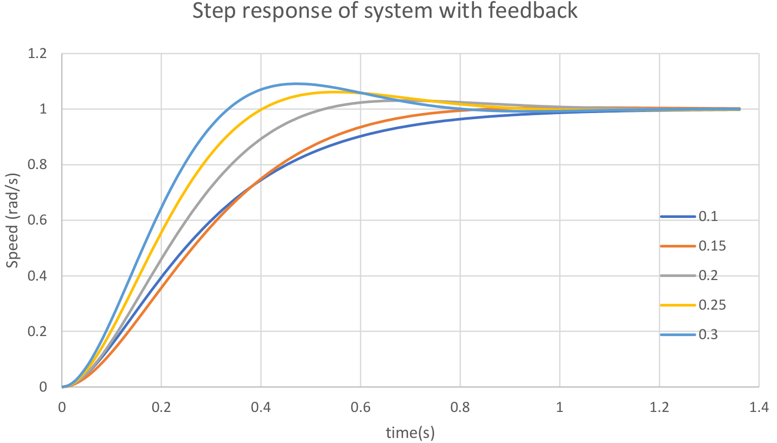
Step response of a feedback system (with different values of compensation gain Ki)
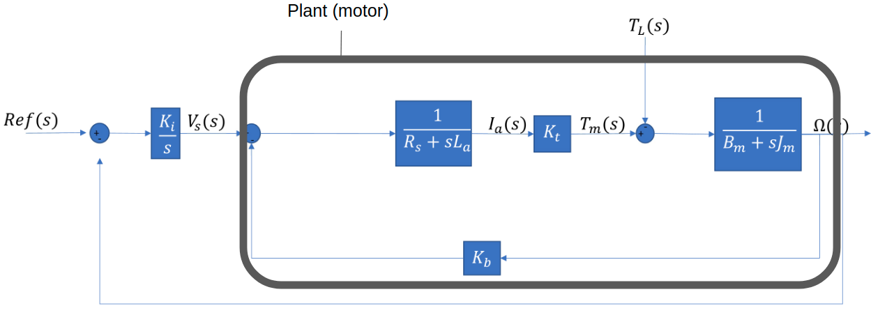
Second order Model with feedback
Unit step response
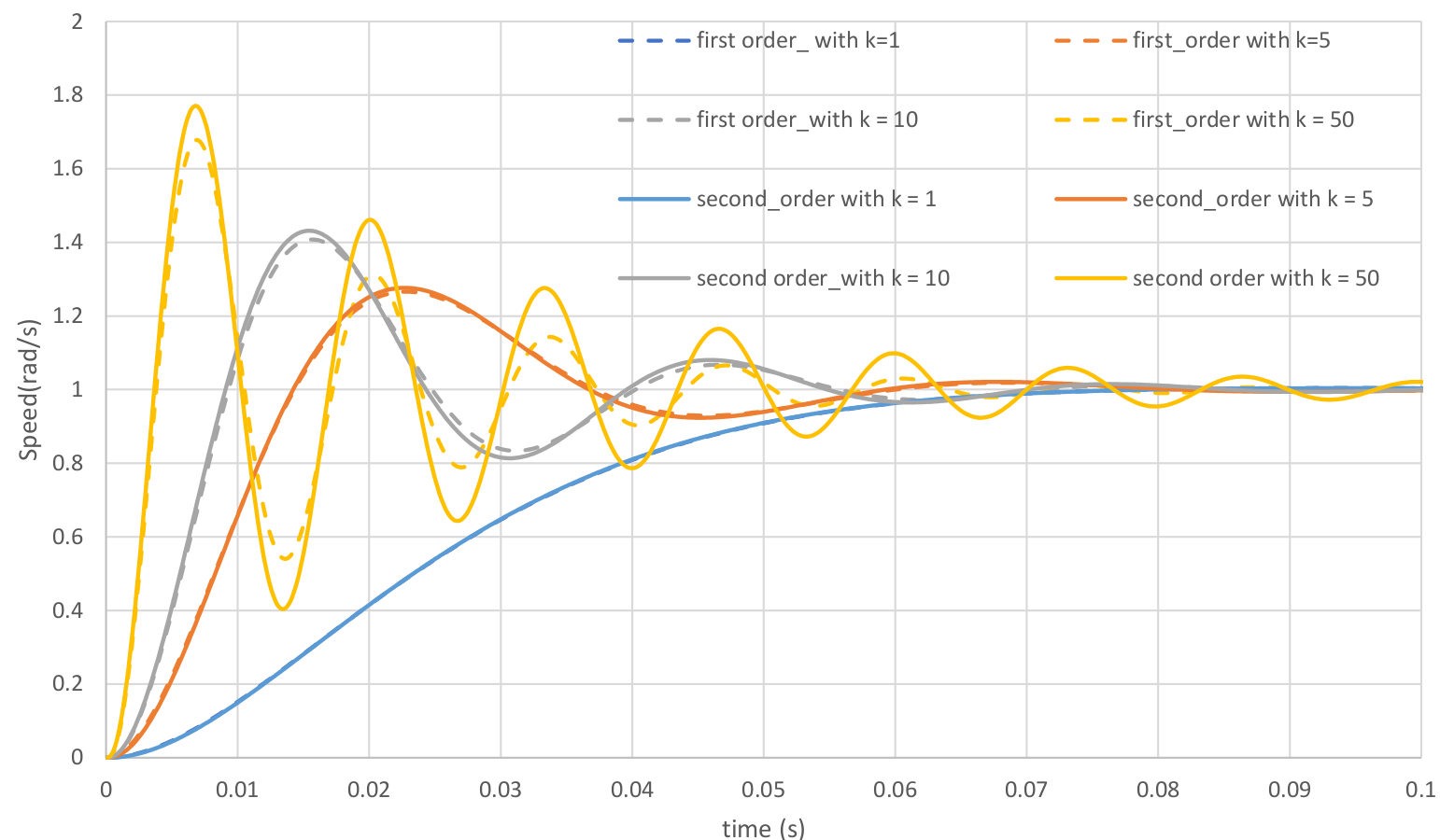
There is a slight difference in the response at higher values of compensation gain
Stability analysis
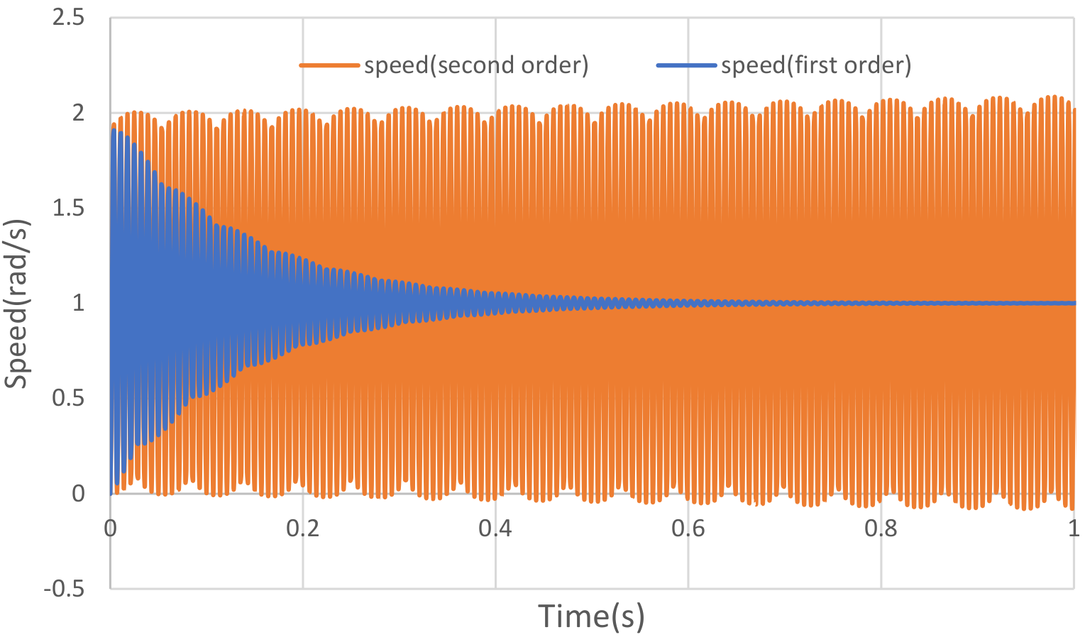
At a compensation gain Ki of 1600
The second order model gives sustained oscillations whereas the first order does not
The first order model is always stable and cannot be used for stability analysis
The second order model gives sustained oscillations whereas the first order does not
The first order model is always stable and cannot be used for stability analysis
Micro-controller based control
In reality the control would be implemented in
software using a micro-controller.
The physical system would something like :
software using a micro-controller.
The physical system would something like :
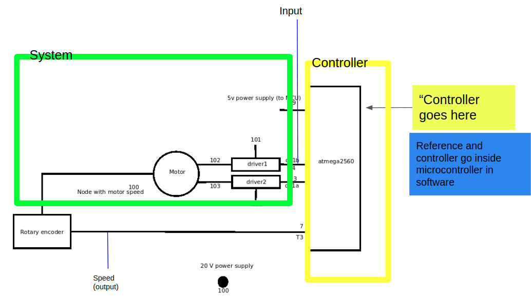
The C-code implements the control system and the exact software (compiled binaries) are used for simulation
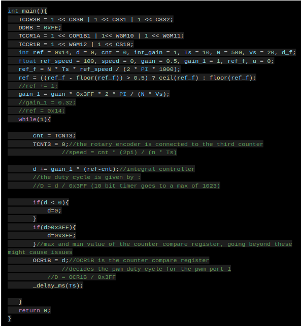
A micro-controller will update the output and sense the input after a sampling period Ts. This sampling period also will have an effect on the output of the system.
The effect of the PWM signal (see the right figure) and sampling time can be observed using tessim simulations.
The effect of the PWM signal (see the right figure) and sampling time can be observed using tessim simulations.
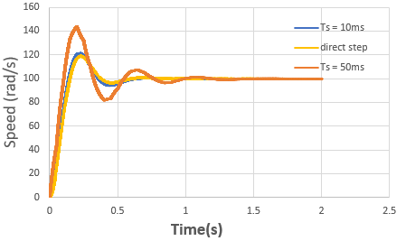
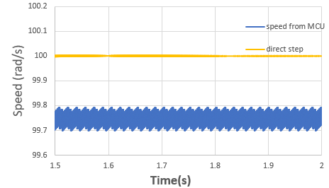
Effect of motor driver
The motor driver will have some delays in giving the output and some finite ramp times .
These delays would introduce a "dead-band" in the motor speed at lower values of duty cycle.
These delays would introduce a "dead-band" in the motor speed at lower values of duty cycle.
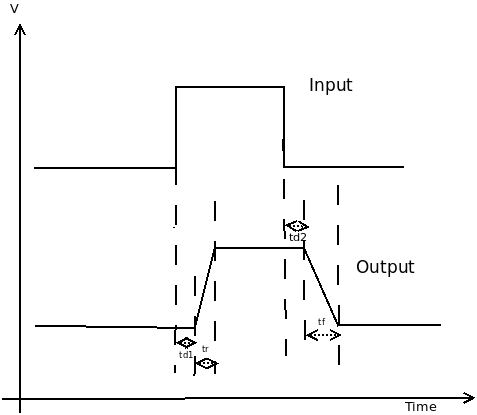
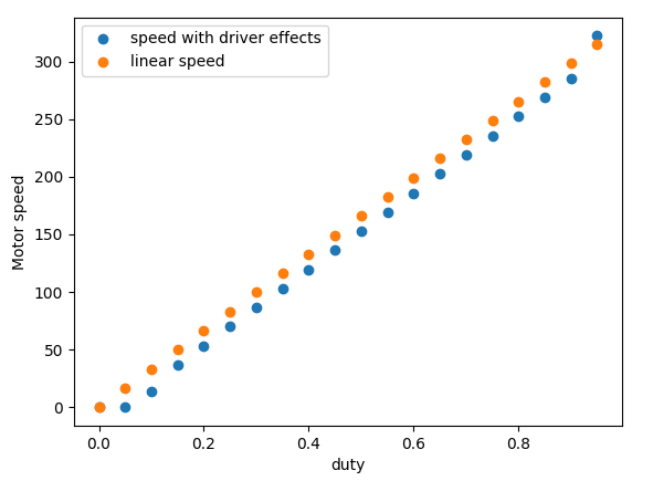
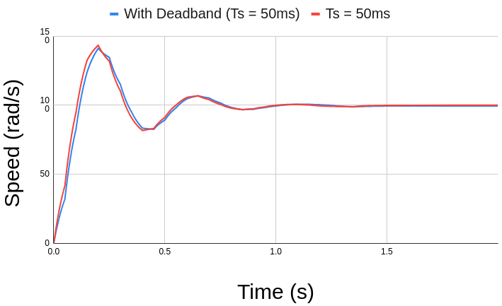
Effect driver effects (dead-band)
1. There will be a slight difference in the response with and without dead-band
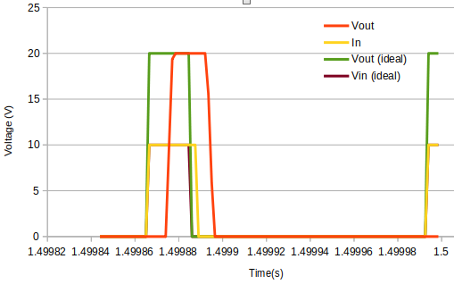
2. Input and output PWM signals for motor driver in ideal and non-ideal case
3. After including the delays from the driver , the input duty cycle (output from MCU) is slightly larger than the ideal case. This is because for the same duty cycle we get lower speed, so for the same speed, a higher duty cycle would be required. This can be seen in the ideal and the actual plots of PWM signal below.
2. Input and output PWM signals for motor driver in ideal and non-ideal case
3. After including the delays from the driver , the input duty cycle (output from MCU) is slightly larger than the ideal case. This is because for the same duty cycle we get lower speed, so for the same speed, a higher duty cycle would be required. This can be seen in the ideal and the actual plots of PWM signal below.